Difference between revisions of "ASLCorporate:Thru-hole Voter Board"
m (Kg7qin moved page Thru-hole Voter Board to ASLCorporate:Thru-hole Voter Board: Moved into protected namespace) |
|||
| Line 1: | Line 1: | ||
| + | [[Category:ASL Corporate]] | ||
<I>This is the first published documentation of the VOTER board and is out of date. It is posted here for historical reasons. The VOTER board is now sold commercially as the RTCM. </i> | <I>This is the first published documentation of the VOTER board and is out of date. It is posted here for historical reasons. The VOTER board is now sold commercially as the RTCM. </i> | ||
==AllStar Link Network -- VOTER Project (Voice Observing Time Extension (for) Radio)== | ==AllStar Link Network -- VOTER Project (Voice Observing Time Extension (for) Radio)== | ||
Latest revision as of 06:23, 6 September 2021
This is the first published documentation of the VOTER board and is out of date. It is posted here for historical reasons. The VOTER board is now sold commercially as the RTCM.
AllStar Link Network -- VOTER Project (Voice Observing Time Extension (for) Radio)
By: Jim Dixon, WB6NIL (SK)
The Official Documentation Package (NO LONGER CURRENT) for the original VOTER system is still available. For current documentation, see the above link for the documentation of the commerically-available product.
For a number years, I have been asked about, and have been considering the possibility of the implementation of a multiple site remote receiver voting system that runs with VOIP on app_rpt/Asterisk. The more I looked into it, the more I realized that it was a FAR from a trivial task.
The main problem to overcome is that when you have muptiple streams of audio information from multiple receivers, you need a concise and accurate way of synchronizing all of the audio, so that if swicthing of streams occurs, there will be no inconsistencies in the audio. This is far more easily done on conventional, RF-linked voting systems, being that the delay between the receiver and the transmitter site is very minimal (basically the speed of light) and is painfuly consistent. Not so on the Internet. The packet delays can be extremely long and varied, and it makes the task of synchronization far more difficult.
The first challenge is to obtain and convey ultra-accurate time information along with the audio data, so that the transmitter site will know what time the signal was received (which may not have much to do with the time it was received at the transmitter site from the Internet). In order to accomplish this, ultra-accurate time information must be made available, and it must be processed in reasonable and consistent time for it to be meaningful.
GPS is the simplest and most cost-effective solution to obtain ultra-accurate time information. For little money (aprox $60US), a Garmin GPS LVC18 module (there are many others, too) may be purchased. It provides an accurate 1 pulse-per-second signal that can be used to synchronize a timing device.
A "host" type computer running Linux (or UNIX, etc) is not appropriate to be used as such a device, since it has absolutely no way of processing external inputs (or anything else, for that matter) in a consistent and predictible time. For application that need to be accurate to hundreds of milliseconds, its fine, but for this purpose, where timing down to individual 125 microsecond audio samples is necessary, it just wont do.
The only reasonable solution is to design hardware to accomplish this. Since hardware design is necessary, I figured that I might as well design a stand-alone board that does all the necessary functions to interface a receiver and a GPS device to an Ethernet with Internet connectivity. Certainly, a peripheral device that attaches to a "host" type comptuer would also be a reasonable solution, but for the same of less cost, it seems reasonable to eliminate the need for a "host" computer at receiver sites alltogether.
The second challenge is determining signal strength (RSSI) information from an attched receiver. Thanks to wonderful technology designed by Steve RoDgers, WA6ZFT, which is a small board that implements a VERY high-quality squelch processor, I was able to take the code and front-end design, include it in my design, and not only is it very good sqlelch processor, but it also is able to provide information from which the signal strength of the received signal may be calculated.
The third challenge is at the transmitter site end (where the app_rpt system is located) taking all of the streams of audio from the various receivers and synchronizing them via included time information, and making a reasonable descision on which stream to "use", based upon signal strength and quality. The synchronization is done with basically a "muti-dimensional jitter buffer" and is implemented in the Asterisk channel driver that I wrote for this application, chan_voter.
The fourth challenge is to facilitate a method of testing the protocol and its implementation within app_rpt. Obviously, there is no way to have a "real" environment available, where there is multiple receiver, mobiles, etc, so a simulator has to be created.
Im VERY sorry and embarassed to say so, but I wrote on in Java (yuch!). It seemed the most reasonable way to accomplish what was necessary. It simulates up to 10 channels of audio, and has "sliders" so that you have full control of "RSSI" and "TIME DELAY" for each channel, in addition to selecting which, if any channels are being sent to the host. You can Run It, if you desire.
I made a new UDP-based protocol for this technology, (called "VOTER"), which may be Viewed here, if desired.
I have successfully written firmware for this device that fully implements the VOTER protocol, converts and encodes the audio stream from the receiver, processes squelch, determines signal strength, and interfaces and quite accurately synchronizes to the GPS receiver.
I have designed and built the stand alone board that is hardware for the receive sites. It's based on a dsPIC33FJ128GP802 processor, and an ENC28J60 Ethernet controller, along with some analog stuff. It is constructed with all thru-hole parts, allowing it to be user-assemblable. The Rev. A boards are have been fabricated, built, and tested. They work very well, and are available currently in small quantity for those wishing to construct them. Please see the Bill Of Materials for a list of parts.
The firmware for this board has been developed and initially tested, and is available for browsing from the AllStarLink github.
VOTER Board Images
Click image to see in Media Viewer.


Photos with Maxtrac
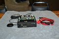
Photo 1
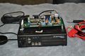
Photo 2
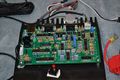
Photo 3
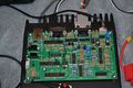
Photo 4
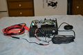
Photo 5
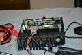
Photo 6
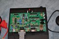
Photo 7


Schematic, Bill of Materials and CAD Files
- The Schematic.
- The Bill Of Materials including Digi-Key part numbers.
- The entire CAD package (including Gerbers).
- The Eagle PCB for layout.
There is a seemingly functional implementation of chan_voter which speaks the VOTER protocol, and allows interface to a node running app_rpt. It includes a "multi-dimensional jitter buffer", which allows all associated streams to be synchronized, analyzed for signal quality, and presented to app_rpt/Asterisk for use in its associated node. Its current version my be Viewed here. It is still very much in the process of being developed.
A test system has been deployed locally (in Madera County, CA, US) and has 5 (may 6 sometime??) receive sites and is being most helpful for testing and verification of the technology and process.
There is now a GUI (Java, yuch!!) based program which allows simulation and experimentation with VOTER streams recorded by the channel driver live on the air (using the 'voter record' command in Asterisk). You can check it out here. If you wish to see it work it with an existing VOTER stream file (4 full-quieting signals), please download this one. To see all the available VOTER stream files, Click Here.
There is also a live VOTER stream monitor JAVA applet avaliable called VoterMon. This applet, along with a distribution server (that chan_voter sends a stream to and allows users of the JAVA applet to connect) lets you make the received VOTER stream directly available to all that want to listen, and see its actions. Click here to see VoterMon in action (monitoring the current VOTER test site in Madera County, CA). The sources for VoterMon and votmond (the distribution server) are available also.
A Surface-mount version of the VOTER board has been produced, and is under final verification. Upon completion, it will be put into production and will be sold as a complete product (fully functional with case, etc) by a third party.
We have had some great success with transmit simulcast. Every VOTER board is capable (if provisioned) to generate time-synchronous audio for the purpose of transmit simulcast (in addition to receiver-site voting). To accomplish simulcast, a GPSDO (GPS-discliplined Oscillator), such as Trimble Thunderbolt, must be used which produces a VERY (supposedly up to 1.5 PPT (yes, TRILLION)) accurate signal at 10 MHz (along with the normal 1PPS and serial GPS location info). Many readily-available good quality transmitters, such as a Motorola Maxtrac/Radius/MSF5000 can be TRIVIALLY modified to take an external reference clock in lieu of its normal internally-generated clock. These radios typically require either a 14.4 MHz or 16.8 MHz reference frequency, so there is now a prototype PLL clock generator board, which takes the 10 MHz clock from the GPSDO and turns it into whatever frequency the transmitter requires for normal operation. Currently in Coarsegold, CA, we have a 2 system voting/simulcast system comprised of Motorola Desktrac repeaters (each a pair of Maxtrac 300 radios) operating very nicely. When you drive through town, its just one working, normal-sounding simulcast repeater system. It's pretty amazing, considering that each Desktrac cost approx $100, each Trimble Thunderbolt cost approx $100, and there is maybe $200 into each VOTER board/clock generator board at each site.